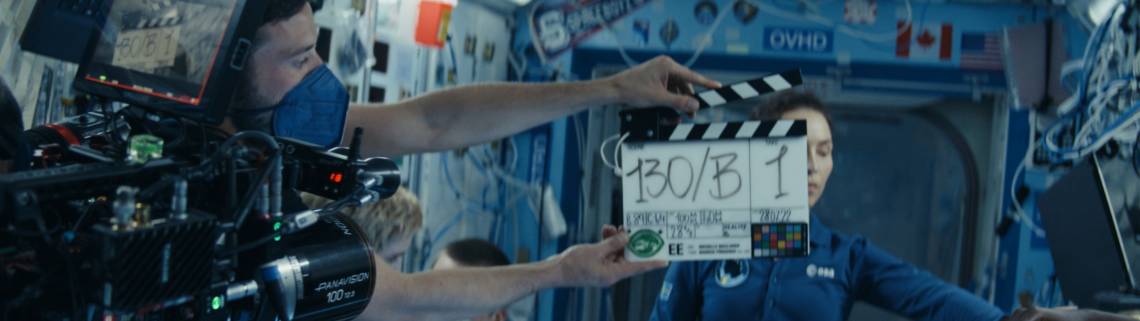
Reverse Power Feed: Fiber-fast DSL Without Breaking the Bank

June 7, 2015, marks the day in which the first 8K high definition (HD) video appeared in YouTube. As HD video content becomes a consumer expectation, and the main On Demand video content suppliers and distributors move to higher and higher resolutions, service providers need to increase their Last Mile capacity so it gets to 1Gbit/s and beyond.
Why G.FAST?
Wireline broadband service providers come typically from two heritages: Cable TV providers, which through the years added Cable Internet services using Data Over Cable Service Interface Specification (DOCSIS) technology, and Telcos, which used Digital Subscriber Line (DSL) technology over their 2-wire telephony lines.
Both Cable and xDSL infrastructures have fiber optics cables in their core and access networks. However, since the deployment of fiber optics is expensive, it is normally delayed as much as possible, and only happens to the extent that is necessary for DOCSIS or DSL aggregation. To put things into perspective, as of 2010, the cost of deploying the 250m closest to the customer premises was $1000.
The DOCSIS 3.0 standard has had support for 1Gbit/s shared throughput since 2006. The December 2013 DOCSIS 3.1 standard allows shared speeds of up to 10Gbit/s, using standard coaxial cable in the last mile.
With customer needs and DOCSIS competition in mind, the ITU ratified the G.FAST standard in December 2014, increasing the maximum DSL speed from the 250Mbit/s supported by VDSL2 to 1Gbit/s. The only drawback G.FAST has is range: it only supports speeds of 500Mbit/s and above at ranges of 100m and below. On top of this, G.FAST loses its edge over VDSL2 data rate beyond 250m. With such a short range, there is great reduction in the number of subscribers served by a single DSL Access Multiplexer (DSLAM): from 100’s of subscribers, to between 1 and 24. This means many more DSLAMs, which move from being at the curb (in what is also known as Fiber to the Curb, or FTTC) to a distribution point (DP), i.e., Fiber to the Distribution point, or FTTdp. So how should they be powered?
Reverse Power Feed: standards and technology
When is RPF needed?
Powering the Distribution Point Unit (DPU) can happen in three ways: local power, forward power and reverse power. When the G.FAST DPU is inside a building, or when it replaces a VDSL2 DPU that had already been deployed close enough to the subscribers, it should be locally powered. However, if it is a new DPU in a location without direct access to power, power needs to be provided either from its core (forward power from the operator’s central office or street cabinets) or from the home it serves (reverse power Feed). Since forward power requires costly maintenance of the aging copper wires as well as deployment of batteries in the already crowded cabinets, bringing power from the home becomes the preferred economical topology.
Reverse Power Feed (RPF) eliminates the need for the Telco to coordinate DPU installation with the local power company, and not only removes the need to pay hundreds of dollars for the smart power meter installation, but also eliminates any complications in acquiring permissions from home owner associations and local municipalities for such power hookup.
RPF Standards and Considerations
Two standardization bodies are specifying RPF, at the time of writing: The Broadband Forum and ETSI. Broadband Forum’s WT-301 “Fiber to the Distribution Point” defines the management interfaces and the usage models for RPF. It relies on ETSI TS 101 548 to define how RPF works.
The key items considered by RPF standards are:
- Migration to RPF: without service disruption, safely (to equipment and to people), without the need to send a technician to the home or to the DPU (a.k.a. “RCR” or “Remote Copper Reconfiguration”).
- Coexistence of Voice service and RPF: safely (to equipment and to people).
- Operation in power outages: cost effectively.
- Capital and Operational expenditures.
- Multi-vendor solution Interoperability: economy of scale.
With these considerations in mind, the latest ETSI draft (as of November 2015) requires the Power Sourcing Equipment (PSE), located at the Customer Premises (CP) to output no more than 60VDC (no need for certified electrician or technician) for all short range power classes. It then defines three maximum PSE output power classes: 21W, 15W and 10W. These classes are necessary to protect equipment connected to the network (which varies from country to country).

Figure 1: Reverse power feed in FTTdp deployment
Power vs Range
The major practical implication of having a limited amount of power at the PSE, and a maximum output voltage of 60V is that the actual range at which the DPU can be deployed from a home will be determined not by the speed that is desired but rather by the maximum power consumption of the DPU from a CPE. The table below describes the amount of power available to the DPU chipset at different cable lengths (in meters). As it can be seen, to support the full 250m range, the DPU chipset cannot consume more than 12.5W at that range.

Table 1: RPF Power availability at different distances.

Figure 2: DPU Available power as function of distance from PSE using 24AWG cable and 350mA PSE current and SELV 57V
Increasing the available power at the DPU side can be achieved using a bigger PSE power supply (i.e. 30W); however for a given cable distance and output voltage, there is an optimum level beyond which increasing the PSE power would result in non-desirable outcome of a lower available power in the DPU.

Figure 3: DPU Available power as function of PSE output power using 250 meters 24AWG cable and SELV 57V.
Analog Phones and RPF
RPF employs the Plain Old Telephone System (POTS) wiring infrastructure already in place at the subscribers’ homes to send power to the DPU. In order for the port to be self-installed by the subscriber, the standard takes into consideration scenarios in which the subscriber connects by mistake a POTS phone directly to a phone outlet that is connected to the RPF system. The RPF Power Sourcing Equipment (PSE) needs to detect the phone and alert the service provider about the phone presence in the RPF network. In case of an off-hook phone, the RPF PSE controller will remove power immediately from the line to avoid safety hazards.
Broadband service providers that provide POTS services to their subscribers and use RPF in a deployment, need to use one of the 3 options: 1) use separate lines for RPF and telephony; 2) use relays to toggle between POTS and xDSL/G.fast services; 3) Install POTS adapters which translate upstream/downstream DC and low frequency POTS signaling into an in-band or out-of-band signaling next to the POTS source and each of the phone outlets (Fig 3).

Figure 4: Analog Phones and RPF coexistance using POTS Adapters (POTSA-E, POTSA-C, POTSA-D).
Power Sharing: is it fair?
Another critical element of RPF is power sharing. The broadband forum has determined that when there is more than 1 active customer on a given DPU, the DPU draws roughly equal power from each line. There are two methods of power sharing that are required, depending on the country customs and the service expectations:
- Equal: the subscribers connected to a DPU share the load equally.
- Equal with battery backup support: when a subscriber’s home is in a power outage situation, the subscriber no longer contributes to the power sharing pool, and its consumption is subsidized by the other subscribers. This method has limitations related to the minimum number of subscribers that need to be delivering power for the system to work minimally, and how the power is allocated when all subscribers are in a power failure mode (and working from batteries).
An additional consideration is the support of MELT: the Metallic Line Test protocol is a requirement in G.FAST installations, and does not operate when RPF power is present. The algorithm employed with RPF at the PSE and at the DPU (for power sharing) needs to take MELT into consideration, as when one line is in MELT checking mode, the other subscribers need to support it.
RPF Technology
Power Sourcing Equipment (PSE)
The power sourcing equipment (PSE) is located at the customer premises. It has the following subsystems:
- Isolated (Boost) Power converter: the isolation is necessary for safety issues. The boost conversion is necessary to improve efficiency, in case the PSE is located inside a CPE with a main internal voltage rail of 12V or 48V. Ideally, the output voltage should be as close to 60V as possible, without surpassing. Table 1 shows an achievable example, assuming an internal voltage of 12V and an isolated Flyback boost converter to 57V.
- PSE Detection, Classification, Powering, Error line condition handling and Protection circuit: This circuit performs all the functions necessary for compliance with the ETSI standard, while preserving human and equipment safety.
Powered Device (PD)
The powered device (PD) is located inside the DPU, and has the following subsystems:
- Voltage Polarity Correction: implemented with either a Diode Bridge (which dissipates P=Vfwd x I) or an Ideal Diode Bridge (which dissipates P=I2xRdson). Typically, an ideal diode bridge saves around 0.5W per port, but is a more expensive device.
- Detection signature: the circuit that identifies itself as an RPF-compatible device. It can be a metallic signature or a communication-based signature. The communication based signature has significant issues to operate in extremely low power, before full power is available from the subscriber, which makes it an impractical solution.
- Classification: unique requirement for RPF which guarantees that PSE would power up only DPU’s which share the same power class level. The classification also eliminate cases of false detection of equipment connected to the line which has a similar signature to that of a DPU.
- Isolated Power Conversion: brings the voltage from the 37V to 57V range down to either 5V or 12V (or whichever voltage the G.FAST or VDSL2 line drivers require), in an isolated (safe) manner.
- Fair Power Sharing: this system perform fair power sharing, measures the voltage/current consumption and indicates whether CPEs are battery powered. Line status and voltage/current measurements are accessible by host for telemetry purposes.
- MELT support: the PD needs to indicate to the PSE that it does not want power, so MELT can be performed. This can be achieved through communication or through inference.
- Dying Gasp: the DPU provide shutdown alert to the Central office right before power is lost. In case possible, the message would indicate the root cause which triggered the event (I.e. power outage, error line condition, etc.).
RPF Injectors vs Embedded RPF
Broadband service providers deploying RPF will not use it in every single instance, as RPF is more costly than local power. Given this consideration, each service provider needs to choose which models of CPE devices are going to be deployed.
Option 1: CPE device without RPF and CPE device with RPF.
- Line port is RPF PSE.
- High level of integration.
- Lowest initial equipment cost.
- RPF Gateways not common.
- Supplied by Service Provider.
- Cannot leverage existing equipment.
- Replaced every 18-24 months.
- When better WiFi is needed.
- When customer comes back from cable.
- Pay for RPF every time.
- Hard to force users to replace existing DSL modems when DP is rolled out.
Option 2: CPE device without RPF and separate RPF injector.
- Less Integrated.
- RPF Injector is part of the DP infrastructure deployment.
- RPF Injector supports VDSL2, G.hn and G.FAST.
- Allows keeping modems commoditised.

Figure 5: RPF Injector vs. Embedded PSE Diagram.

Table 2: RPF Injector vs. Embedded RPF comparison summary.
RPF is a critical technology, enabling service providers to upgrade their ADSL subscribers to the new VDSL2 and latest G.FAST standard so they can receive up to 1Gbps data rates over copper which is necessary for Ultra HD TV and other broadband services.
You might also like...
Essential Guide: Broadcast And The Metaverse
The technology underpinning the Metaverse is providing opportunities for broadcasters today. As the Metaverse develops, broadcasters will be able to gain massively from the enhanced immersive experience it promises to offer.
Learning From The Experts At The BEITC Sessions at 2023 NAB Show
Many NAB Shows visitors don’t realize that some of the most valuable technical information released at NAB Shows emanates from BEITC sessions. The job titles of all but one speaker in the conference are all related to engineering, technology, d…
Empowering Cloud Through Microservices - Part 2
Achieving higher levels of scalability and flexibility demands a hybrid approach were microservices run in the cloud, on- and off-prem. Also, common APIs hide the complexity of the infrastructure from the user to provide a seamless operation.
System Showcase: Gravity Media Opens New Production Centre In London For Remote And On-Prem Projects
Production and media services company Gravity Media has just completed the first phase of technology integration at its new London Production Centre White City, located on the fifth floor of The Westworks building in London. The state-of-the-art facility, officially opened…
Interlace: Part 3 - Deinterlacing
Now that interlace is obsolete, we are left only with the problem of dealing with archive material that exists in the interlaced format. The overwhelming majority of video tapes, whether component or composite, analog or digital, would be interlaced.